Choosing between optical and electrical interfaces is a crucial decision when building high-performance networks. The pots, cables, and connectors are completely different, and there are pretty vital nuances in how they function and key areas in which either excel. The question, or rather decision, must be made before any infrastructural equipment is purchased. This is the basis for building your system network.
How Optical Interfaces Work
Optical interfaces transmit data using lightwaves through glass or plastic fiber optic cables. These optical transceiver modules receive the electrical signal output from your device and translate it into light pulses. These pulses make their way through fiber optic cables and reach photodetectors, where they are converted once again into electric signals that can now be processed.
Transmission through lightwave is super-efficient for long-distance transmitting and entirely free from electromagnetic interference. These interfaces are generally used in data centers for long-haul telecoms when both bandwidth and reach are of primary importance.
How Electrical Interfaces Work
The electrical interface designates the sending of data through electrical signals over copper conductors. These can be PCB traces (on a backplane), DACs, or copper patch cables. Driver chips play an essential role in the transmission of data because they send the modulated voltage levels throughout the cable.
Electrical interfaces provide optimal service for fast networks at short distances, deployed inside racks and on internal backplanes for a lower-speed, low-latency network setup. Additionally, it is far cheaper than its optical counterpart, and it also consumes less power.
Interface and Connectivity
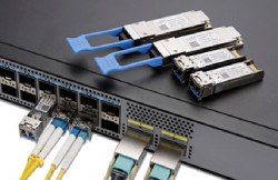
Even if they may use the same form factor, such as SFP+, electrical and optical interfaces have different physical requirements. Each has its types of ports and connectors, and they aren’t interchangeable. Optical interfaces use fiber optic connectors like LC, SC, or MPO, of course, depending on the type and application. They are more sensitive to physical stresses, dirt or dust, and require more precise alignment.
Electrical interfaces use copper connectors or attach straight onto the paddle cards, backplane connectors or DAC ends. This is a more user-friendly setup, as they are easier to plug in and have less risk of damage from external forces.
Signal Parameters and Performance Differences
Optic signals travel as light, thus can perform over longer distances and are not affected by outside noise or interference. They can suffer from dispersion or attenuation over distance, but this is predictable and can be managed. The electric signals tend to degrade over distance due to resistance, capacitance and crosstalk. Therefore, they are ideal for shorter distance transmissions, where they are fast and have low latency. They can also generate electromagnetic interference, or EMI, which can limit performance.
Transmission Distance and Reach
This is where the gap widens significantly. Optical interfaces easily handle up to 100 meters using multimode fibers. But using LR, ER and ZR modules can see the range go up to 10 to 40 km, and long-haul DWDM systems can handle thousands of kilometers.
Electrical interfaces, on the other hand, are far shorter. Passive DACs can handle 5 to 7 meters, and interfaces using active copper solutions can do 10 to 15 meters.
Component Complexity and Cost
Optical modules require:
- A laser or VCSEL to generate light
- A photodetector for conversion
- Precision optics for alignment
- Thermal control to maintain signal quality
The initial higher cost and increased handling considerations punish the fiber optics. But it pays off for performance with higher speeds and distance.
Electro-optic interfaces are simple by design. With fewer active components, less precision is needed when integrating with existing copper infrastructure. Electrical interfaces, being cheaper and drawing less power, make sense for short hops and save money overall for big deployments.
Power Consumption
High-speed optical modules need a lot more power, especially for advanced diagnostics and temperature management. With CMIS-managed modules and thermal engineering, modern optical interfaces can reduce their power consumption even while performing at speeds of over 100G.
But they still require more power than electrical interfaces, which can use passive DACs or backplane connections to mitigate the power consumption. These are ideal for power-sensitive environments.
Where Each One Belongs
Electrical interfaces shine in short, controlled environments: inside servers, between top-of-rack switches and adjacent gear, or within single-chassis systems. They’re quick, cheap, and efficient, and there’s no need to mess with fiber cleaning or alignment.
Optical interfaces dominate anywhere distance, scalability, and bandwidth come into play. You’ll find them in:
- Leaf-spine network cores
- Data center interconnects
- Long-haul ISP and metro networks
- AI/ML cluster backbones
- High-performance trading systems where jitter and loss matter
The best networks often use both, layering electrical interfaces where possible and scaling with optics as demands increase.